In bulk material handling systems for cement production, mineral processing, and food manufacturing, a
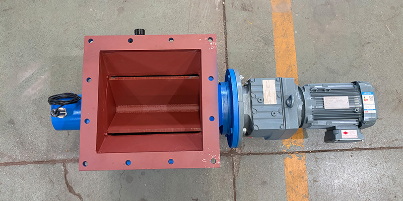
rotary airlock valve — commonly referred to as a rotary gate, rotary feeder, or industrial rotary valve — serves as a critical dual-function component. It delivers stable, adjustable volumetric feeding for dry powders and granular materials while maintaining consistent pressure isolation between separate process zones. This unique dual functionality makes it indispensable for pneumatic conveying, industrial dust collection, and silo discharge operations across heavy industrial facilities.
If you have explored our core technical guide on
rotary gate types and industrial applications, you will be familiar with the four primary valve configurations: drop-through, blow-through, heavy-duty wear-resistant, and sanitary quick-clean rotary valves. While understanding product classifications builds fundamental knowledge, most on-site unplanned downtime, unstable feeding performance, and premature equipment wear stem from improper specification, incorrect field application, and insufficient routine maintenance. This practical guide solves these common pain points with field-verified engineering best practices.
Designed exclusively for process engineers, plant maintenance teams, and industrial procurement specialists, this article covers six high-cost rotary airlock valve selection mistakes, complete field troubleshooting solutions, long-term maintenance guidelines, and a standardized selection workflow. All recommendations apply to positive and negative pressure pneumatic conveying systems, baghouse dust collection setups, and large-scale silo bulk feeding workflows.
How a Rotary Airlock Valve Works in Industrial Bulk Handling
To avoid specification errors and operational failures, it is critical to understand the real-world working principle of a rotary feeder in industrial environments.
A standard rotary airlock valve consists of a precision-machined cylindrical housing and a continuously rotating multi-vaned rotor. As the rotor spins, hollow pockets between the vanes capture bulk materials through the top inlet. Depending on the valve design, materials are either gravity-discharged from the bottom outlet or swept out by high-velocity conveying air in pneumatic transport pipelines.
The precision-controlled tiny clearance between rotor tips and the valve housing creates a reliable airlock seal. This key structural feature prevents cross-leakage of air and process gas between equipment with different pressure levels, effectively isolating ambient-pressure silo hoppers from high-pressure conveying pipelines and negative-pressure dust collectors. Meanwhile, adjusting rotor RPM regulates material output, enabling precise, stable volumetric feeding for consistent production throughput.
A vital industry distinction separates lab data from field performance: manufacturer catalog throughput ratings are tested under ideal 100% rotor pocket filling conditions. In actual industrial operation, multiple environmental and mechanical factors limit filling efficiency, making real-world performance significantly different from theoretical parameters — a core factor for accurate rotary airlock valve sizing and specification.
Six Costly Rotary Airlock Valve Selection Mistakes
Nearly all premature component wear, feeding instability, and excessive air leakage issues originate from avoidable selection errors during the design and procurement phase. Below are the six most common, financially impactful mistakes in rotary gate specification, paired with professional, field-proven corrective practices.
1. Sizing to Ideal Catalog Capacity Instead of Real-World Pocket Fill Rate
This is the most prevalent and problematic sizing mistake for industrial rotary airlock valves. All manufacturer datasheets calculate maximum throughput based on 100% rotor pocket filling, a strict laboratory condition that never occurs in actual field operation. For conventional gravity discharge and standard pneumatic conveying systems, the real pocket fill efficiency of rotary valves only ranges from 50% to 70%.
Material flowability, rotor operating speed, hopper inlet geometry, and system pressure differentials directly impact filling efficiency. Engineers who size valves strictly according to ideal catalog ratings force equipment to run at maximum RPM to meet production demands. This accelerates mechanical wear, causes fluctuating feed rates, and triggers frequent underfeeding during changes in material bulk density or flow characteristics.
Best Practice: Moderately oversize the rotary feeder to offset real-world filling efficiency losses. Operating the valve at a stable low-to-medium RPM minimizes mechanical wear and maintains consistent volumetric feeding. Equip the valve with a Variable Frequency Drive (VFD) to flexibly adjust feed output to match real-time production requirements.
2. Underestimating Abrasive Wear from Industrial Bulk Materials
In cement and mining operations, bulk materials including cement clinker, crushed mine ore, silica sand, and slag deliver strong abrasive properties. Standard cast iron and carbon steel rotary gate models lack sufficient wear resistance, leading to rapid internal erosion during long-term processing of abrasive media.
Worn rotor tips and degraded housing inner walls expand the sealing clearance, resulting in severe air blow-by. Excessive air leakage further disrupts feeding stability and accelerates component degradation, forming a vicious cycle that shortens equipment service life and increases routine maintenance and replacement costs.
3. Using Ambient-Temperature Clearance for High-Temperature Processes
A 0.1mm rotor tip clearance delivers optimal pressure sealing performance for room-temperature processing of non-abrasive dry powders. However, many industrial workflows handle high-temperature materials such as hot ash and calcined minerals, which introduce unique thermal expansion challenges.
Rotors and valve housings feature different thermal expansion coefficients. Retaining standard ambient-temperature clearance for high-temperature operation causes rotor jamming, shaft friction damage, and motor overload tripping, often leading to unplanned production shutdowns and permanent equipment failure in severe cases.
Fix: Appropriately enlarge rotor tip clearance based on the system’s maximum operating temperature. Consult professional manufacturers for precise thermal expansion calculation data matched to your specific valve model and working conditions to ensure safe, stable high-temperature operation.
4. Deploying Drop-Through Rotary Valves for Cohesive, Sticky Materials
Drop-through rotary valves are the most universal option for general bulk handling, relying entirely on gravity to empty rotor pockets. This design performs perfectly for free-flowing, non-cohesive dry powders such as cement, fly ash, and quicklime.
However, sticky, cohesive, or highly aerated fine powders easily adhere to rotor pocket inner walls and cannot be fully discharged via gravity. Residual materials harden over time, reducing effective feeding capacity and triggering frequent rotor blockage and operational failures.
Fix: Install blow-through rotary valves for sticky and aerated bulk materials. The pneumatic conveying pipeline runs directly through the valve’s lower casing, using high-velocity airflow to thoroughly sweep residual materials from rotor pockets. Additionally, this compact design requires minimal vertical installation headroom, making it ideal for retrofitting existing production lines with limited layout space.
5. Overlooking Sanitary Standards for Food, Dairy & Pharmaceutical Production
Food processing, dairy powder production, and pharmaceutical manufacturing enforce strict hygiene and cross-contamination prevention regulations. Standard industrial rotary valves require full detachment from connecting pipelines to remove the rotor for cleaning, resulting in lengthy downtime and incomplete sanitization.
Frequent product changeovers in these industries amplify residual contamination risks, failing to meet industrial compliance standards and compromising final product quality.
Fix: Adopt sanitary quick-clean rotary gates with a slide-out rotor assembly. Operators can extract the entire rotor along built-in guide rails without removing the valve body from the pipeline, completing thorough sanitization in minutes. All wetted parts feature polished 316 stainless steel with zero dead corners, eliminating cross-contamination risks for batch production.
6. Ignoring System Differential Pressure Rating Limits
Standard industrial rotary valves have a maximum differential pressure rating of 15 PSI, suitable for most conventional low and medium-pressure bulk handling systems. High-pressure pneumatic conveying workflows often exceed this standard rating.
Excessive system pressure causes gas blow-back through rotor gaps, pushing fine powders upward into silos and hoppers, destabilizing conveying airflow, and triggering pipeline blockages and costly unplanned downtime.
Fix: Confirm the maximum differential pressure of your pneumatic conveying and dust collection systems during the specification phase. Upgrade to reinforced heavy-duty rotary airlock valves for high-pressure working conditions to maintain reliable sealing and consistent feeding performance.
Rotary Airlock Valve Troubleshooting: Complete Field Reference Guide
Most rotary feeder operational faults can be quickly diagnosed and resolved through simple on-site symptom observation. The following structured troubleshooting table summarizes common field failures, root causes, and targeted solutions for maintenance and engineering teams.
Symptom | Likely Cause | Corrective Action |
Excessive air leakage & pressure drop across valve | Worn rotor-housing clearance, degraded end-plate seals, operation exceeding standard pressure rating | Inspect and replace worn rotors and seals; recalibrate rotor tip clearance; upgrade to heavy-duty pressure-resistant models for high-pressure systems |
Actual throughput lower than design specification | Excessive rotor RPM reduces pocket filling efficiency; hopper material bridging; cohesive material residue buildup | Adjust rotor speed to the optimal operating range; eliminate hopper bridging issues; replace with blow-through rotary valves for sticky materials |
Rotor jamming & motor overload tripping | Foreign metal particles or oversized materials entering the valve; thermal expansion friction; hardened material buildup | Install upstream magnetic separators and screening devices; adjust clearance for high-temperature operation; clean internal rotor and housing residues thoroughly |
Rapid internal component wear | Abrasive materials without wear-resistant protection; long-term high-speed rotor operation | Install wear-resistant liners and carbide coatings; reduce operating RPM; adopt closed-end rotor structure for abrasion resistance |
Persistent material buildup in rotor pockets | Damp or cohesive bulk materials; inefficient rotor pocket structural design | Add inlet vibratory devices to promote material flow; optimize pocket profile; switch to self-cleaning blow-through rotary valve design |
Batch-to-batch cross-contamination | Complicated disassembly and cleaning structure; internal dead corners trapping residual materials | Replace with sanitary quick-clean rotary gates; establish standardized batch cleaning operating procedures |
Proactive Maintenance Habits to Maximize Rotary Feeder Service Life
A high-quality rotary airlock valve can deliver years of stable, low-failure operation with scientific, routine maintenance, while irregular upkeep leads to frequent malfunctions and high equipment replacement costs. These practical maintenance habits help industrial plants minimize downtime and extend overall equipment lifespan.
1. Conduct regular rotor tip clearance inspection. Component wear occurs gradually during continuous operation. Perform quarterly clearance checks with a feeler gauge, record baseline data at installation, and track long-term changes. Early detection of enlarged clearance prevents severe air leakage and progressive performance degradation.
2. Prevent foreign object entry. Welding slag, loose bolts, and other workshop debris can scratch rotor vanes and damage valve housing interiors. Install magnetic separators and screening devices at silo and hopper inlets to purify incoming materials and protect core valve components.
3. Standardize bearing lubrication. Strictly follow the manufacturer’s recommended lubrication cycle. Both insufficient and excessive grease filling damage bearings and seals; over-lubrication also causes product contamination in sanitary food and pharmaceutical production scenarios.
4. Maintain optimal moderate rotor speed. Avoid long-term high-speed operation above 30 RPM, which accelerates mechanical wear and reduces pocket filling efficiency. Utilize a VFD drive to match rotor speed to actual production demand, keeping operation within the 15–25 RPM optimal range.
5. Prepare wear part spares in advance. For high-abrasion working conditions, rotor tips, wear liners, and seals are consumable components. Reserve spare parts on-site and arrange scheduled replacement during planned shutdowns to eliminate unplanned production halts.
Step-by-Step Rotary Airlock Valve Selection Framework
Follow this standardized engineering workflow to select the most suitable rotary gate for your bulk material handling project, eliminating subjective judgment and specification errors.

 English
  Russian
  French
  Portuguese
  Arabic
  Spanish
  Japanese