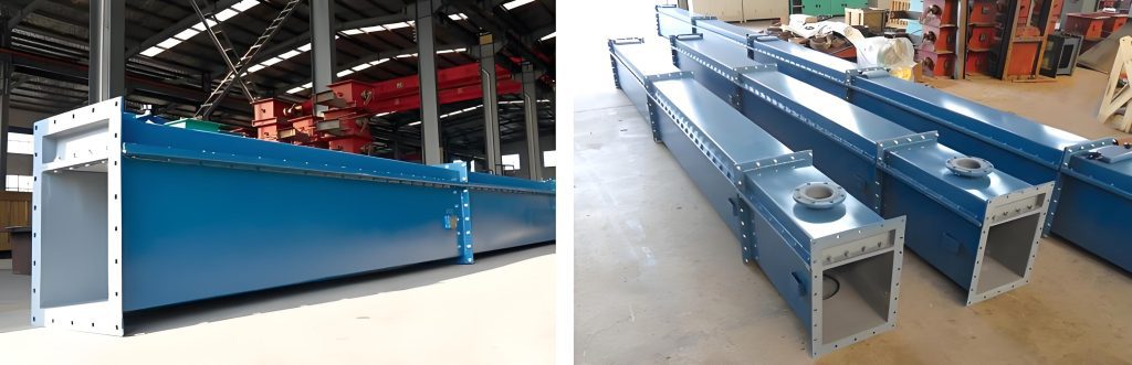
Cemento transportadores de deslizamiento neumático move powdered materials using a combination of fluidization and gravity. They have a simple structure, use little energy, and contain no moving parts. Because of these advantages, industries widely use them in cement plants to transfer material between silos, from silos to mills, and from dust collectors to storage bins.
Selecting and designing an air slide requires a systematic approach. You must focus on delivery needs, material characteristics, and operational stability to determine the core parameters and key configurations.
Part 1: Calculating the Key Parameters
1. Determine Conveying Capacity
The conveying capacity is the primary basis for selection. You must match this capacity with the production line’s actual needs, including a 10%-20% margin. Also, consider the incline angle and the cross-section size of the trough.
Incline Angle Impact: The critical incline angle for cement is 4°. If the angle is smaller, conveying can stop. The common range is between 4° and 12°. A greater angle means a higher capacity. For example, an XZ400 series air slide can move about 130 t/h at 4°, and this can reach 455 t/h at 12°.
Selecting Cross-Section Size: Once you set the angle, the trough width determines the capacity level. Common widths are 200mm, 315mm, 400mm, and 500mm. You should select the size based on your calculated capacity.
2. Match Air System Parameters
Compressed air provides the power for fluidization. You must carefully match the air pressure and air volume.
Air Pressure (P): The pressure must overcome the resistance from the permeable layer, the material bed, and the system itself. For cement, you typically need 4-5.5 kPa. For long distances or dense materials, you can increase this to 6 kPa.
Air Volume (Q): This relates to the trough’s cross-sectional area and the material properties. Cement usually needs 1.5-2 Nm³/(h·m²) of air per square meter of trough area. Based on this, you can select a suitable low-pressure centrifugal fan or Roots blower.
Part 2: Selecting and Configuring Key Components
1. Select the Permeable Layer
The permeable layer is crucial for good fluidization. You need to balance permeability, wear resistance, and heat resistance.
Material Choice: For cement, choose a synthetic fiber layer. It is usually 4-6mm thick and can withstand temperatures up to 150°C. This suits normal cement temperatures (≤120°C) and resists clogging better than traditional canvas.
Easy Replacement: Choose a modular design with a bolted structure. This makes later maintenance and replacement much easier.
2. Design the Casing and Support Structure
- Casing Material and Build: Use welded Q235 steel plates, 3-5mm thick. The upper and lower casings bolt together to form a sealed chamber. You must seal the joints to prevent dust leaks.
- Support Setup: Install support stands every 2-3 meters. Set the stand height to ensure a consistent incline along the entire length. This prevents local material buildup from angle changes.
3. Configure Auxiliary Components
Air Intake System: Install air inlets at set intervals along the bottom of the trough. Fit these with valves to control the air flow and ensure even distribution. Also, place a filter at the fan inlet to stop impurities from clogging the permeable layer.
Venting and Dust Control: Place a vent at the high end of the trough. Connect this to a bag filter. This prevents dusty air from escaping and also balances the internal pressure.
Cleaning Access: Install clean-out doors at the low end and at bends. These allow for regular cleaning of accumulated material and help prevent blockages.
Part 3: Important Design Considerations and Risk Control
1. Adapt to Material Properties
Keep the moisture content in the cement below 1%. Damp material can stick to the permeable layer and cause blockages. Also, prevent large foreign objects from entering by installing a screen or grate at the feed inlet.
2. Plan a Rational Layout
Keep single sections shorter than 30 meters. For longer distances, use multiple sections and connect them with bends. Match the bend angle to the main trough. Avoid frequent direction changes to reduce material impact and buildup risk. At the high-end feed inlet, add a buffer structure to protect the permeable layer from direct material impact.
3. Include Maintenance and Monitoring Features
Install inspection windows along the trough’s length. These let operators visually check material flow. For monitoring, place pressure sensors above the permeable layer. Changes in pressure can warn you of potential blockages. Also, install a pressure gauge at the fan outlet to monitor stability.
Part 4: Summary of the Selection and Design Process
Define Requirements: Determine basic parameters like cement volume, distance, and lift height.
Calculate Parameters: Based on capacity, decide the trough width and incline angle. Then, calculate the required air pressure and volume to select a fan model.
Select Components: Choose the permeable layer, casing, and auxiliary parts according to the material and operating conditions.
Optimize Layout: Finalize the trough path, support stands, and air supply system design.
Check for Risks: Verify suitability for material moisture, check pressure loss, and ensure easy maintenance. Implement preventive measures.