Le ciment système de chargement en vrac est un équipement spécialisé pour la poudre de ciment. Il permet le chargement automatique du ciment en vrac sur les véhicules. Il y a 5 silos à Huaxin (LiJiang) Cement. Nous avons effectué les rénovations correspondantes sur 5 systèmes de chargement de ciment en vrac, ce qui a permis de réduire les émissions de poussières, de purifier l'environnement de travail et d'améliorer l'image de l'entreprise sur le marché.
Composition structurelle de la machine de chargement de ciment en vrac
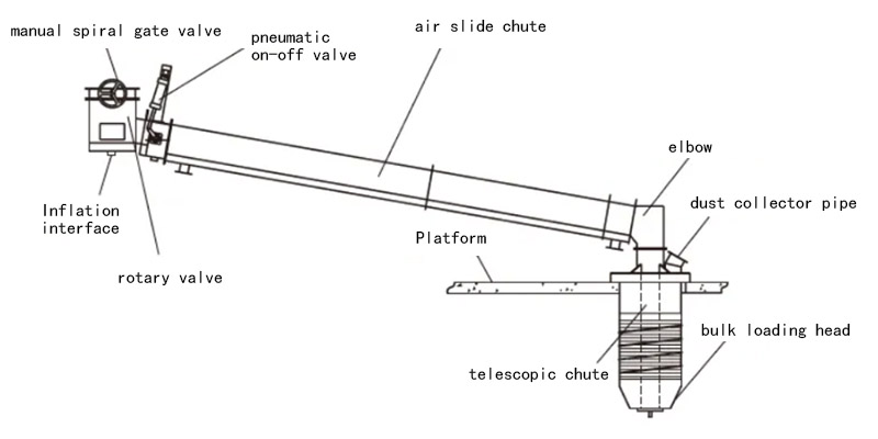
Le système de chargement en vrac du ciment est principalement composé d'un alimentateur rotatif, d'une vanne manuelle à spirale, d'une vanne pneumatique marche-arrêt, d'une goulotte à air, d'une goulotte télescopique à double couche, d'une tête de chargement en vrac, d'un interrupteur de contrôle automatique du niveau de matériau, dépoussiéreur et une armoire de commande électrique, etc.
L'alimentateur rotatif peut faire en sorte que le ciment s'écoule de manière fluide des silos. Il remplit les fonctions de déchargement stable, de mélange et de déblocage de la trémie.
La vanne manuelle à spirale peut couper l'alimentation en ciment lorsque le système de chargement en vrac est en cours de maintenance. Mais le robinet-vanne manuel à spirale est généralement ouvert pendant le chargement.
Le corps de la vanne pneumatique tout ou rien est une structure en forme d'arc. Cela permet au ciment de s'écouler en douceur et de contrôler instantanément le démarrage et l'arrêt du processus de remplissage.
La tête de chargement est composée d'un treuil électrique et d'une goulotte télescopique. Le remplissage est contrôlé par un interrupteur de contrôle du niveau de matériau, et lorsque le remplissage est terminé, un signal de commande est envoyé pour fermer la vanne pneumatique marche-arrêt et arrêter le chargement.
Processus de fonctionnement du système de chargement de ciment en vrac
1. positionnement
Le chauffeur conduit le camion-citerne à ciment en vrac sous le système de chargement en vrac fixe. Il aligne l'ouverture d'alimentation du camion-citerne directement sous la tête de chargement. L'opérateur active le dispositif d'élévation. Cela permet à la tête de chargement, reliée à la goulotte télescopique à double couche, de descendre dans l'ouverture d'alimentation du camion-citerne. Après avoir assuré l'étanchéité entre la tête de chargement et l'ouverture d'alimentation de la citerne, l'interrupteur de commande coupe automatiquement l'alimentation électrique. Le processus de positionnement est ainsi terminé.
2. déchargement
Une fois que la tête de chargement est dans la position désignée, tous les équipements de la machine de chargement en vrac sont mis en marche de manière séquentielle. Le ciment est déchargé de l'entrepôt à l'état fluide. Le ciment fluidifié passe par la vanne pneumatique marche-arrêt et la goulotte à air dans le chargeur en vrac, et s'écoule dans le réservoir de stockage par la tête de chargement. Le dépoussiéreur absorbe les gaz et les poussières expulsés par le transport du ciment et le camion-citerne, garantissant ainsi un environnement de travail sans pollution. Les poussières collectées sont envoyées dans un silo pour être recyclées.
3.Contrôle du niveau des matériaux
Lorsque le ciment dans le camion-citerne atteint la hauteur de remplissage, la conduite d'air connectée, installée au sommet de la tête de chargement, est enfouie dans le ciment. La pression de l'air augmente, activant le contrôleur de pression, qui envoie un signal de contrôle de charge complète, fermant la vanne pneumatique tout ou rien pour couper la source de matériau et arrêter le processus de chargement. La goulotte télescopique et la tête de chargement sont alors soulevées pour terminer le chargement. Pendant ce temps, un relais de temporisation est activé pour permettre au dépoussiéreur de continuer à collecter la poussière.
4. Départ du camion-citerne
Une fois le délai écoulé (généralement de 4 à 6 secondes), le dépoussiéreur s'arrête. La cloche du site sonne, signalant la fin du processus de chargement en vrac. Le camion-citerne s'éloigne.
Problèmes persistants
(1) Il y a un “agglutinement du ciment” pendant le processus de chargement. Ce ciment aggloméré est chargé dans le camion-citerne. Il est ensuite transporté vers la station de mélange ou le chantier de construction pour être utilisé directement. Cela affecte la qualité du ciment distribué et entraîne des réclamations de la part des clients.
(2) Lors de l'élévation et de la descente de la tête de chargement, de la poussière tombe de la tête de chargement. Cette pollution affecte le milieu environnant.
(3) Pendant le chargement, le système de chargement du ciment en vrac provoque souvent des émissions de poussière par l'ouverture du camion-citerne. Cela a un impact important sur les valeurs mesurées des PM2,5 et PM10 dans l'environnement.
Analyse des causes
(1) Le ciment dans le silo s'agglomère souvent. Cela est dû à des facteurs tels que les fuites de pluie du toit, la condensation due aux différences de température dans les murs, les températures de stockage élevées et l'eau cristalline provenant du gypse et des matériaux mélangés. Le ciment aggloméré est généralement peu structuré et se casse facilement. Toutefois, certains agglomérés sont plus étroitement liés. Leur utilisation directe peut affecter la qualité du ciment.
(2) Après la fermeture de la vanne de déchargement pneumatique, une partie du ciment reste dans la glissière d'air entre la vanne et le dispositif de déchargement à coude. Lors de l'élévation et de la descente de la tête de chargement, les vibrations ou la pression d'air résiduelle provoquent l'écoulement du ciment dans la glissière d'air et sa chute sur le sol, ce qui entraîne une pollution.
(3) Au cours du processus de chargement en vrac, nous avons mesuré une forte pression négative dans le tuyau de collecte des poussières de la tête de chargement. Cela indique que la poussière s'échappe de l'ouverture d'alimentation du camion de vrac parce que l'espacement entre les tubes intérieurs et extérieurs de la tête de chargement est trop faible. L'espacement à l'extrémité inférieure de la tête de chargement est encore plus petit. Cela réduit la section de passage de l'air dans le tuyau d'entrée du dépoussiéreur. En conséquence, la pression négative dans la goulotte télescopique à double couche augmente, ce qui réduit le flux d'air dans le dépoussiéreur. Cela crée un phénomène de pression positive “d'échappement de la poussière” dans le réservoir de stockage du camion-citerne.
Mesures de rénovation technique
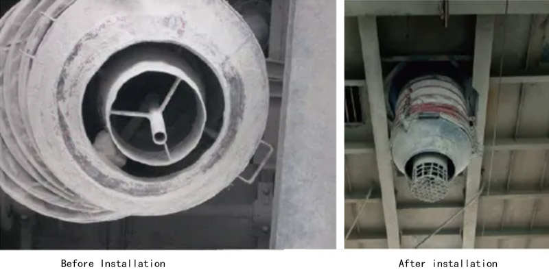
1. installer un tamis sur la tête de chargement en vrac
Nous concevons un grillage à installer au niveau de l'orifice de décharge de la tête de chargement. Le grillage a une hauteur de 200 mm. Il comporte un trou carré sur le côté, mesurant 30 mm de largeur et 20 mm de hauteur. En outre, le fond est percé d'un trou circulaire d'un diamètre de 25 mm. Lorsque les morceaux de ciment tombent sur le grillage à l'intérieur du camion-citerne, la plupart des morceaux sont écrasés. Seuls quelques gros morceaux obstinément collés restent sur le grillage.
Une fois le processus de chargement en vrac terminé et la tête de chargement soulevée, il est facile de remarquer les résidus. Ces résidus peuvent être nettoyés rapidement avant le prochain processus de chargement.
2. ajouter une autre vanne pneumatique tout ou rien
Nous avons installé une vanne pneumatique marche-arrêt à l'extrémité de la goulotte d'évacuation du toboggan à air. Il y a deux vannes pneumatiques tout ou rien réparties aux deux extrémités de la goulotte. Ces deux vannes s'ouvrent et se ferment simultanément pour empêcher le matériau de se répandre pendant le processus de levage de la tête de chargement.
Nous avons installé une vanne pneumatique marche-arrêt à l'extrémité de la goulotte d'évacuation du toboggan à air. Il y a deux vannes pneumatiques tout ou rien réparties aux deux extrémités de la goulotte. Ces deux vannes s'ouvrent et se ferment simultanément pour empêcher le matériau de se répandre pendant le processus de levage de la tête de chargement.
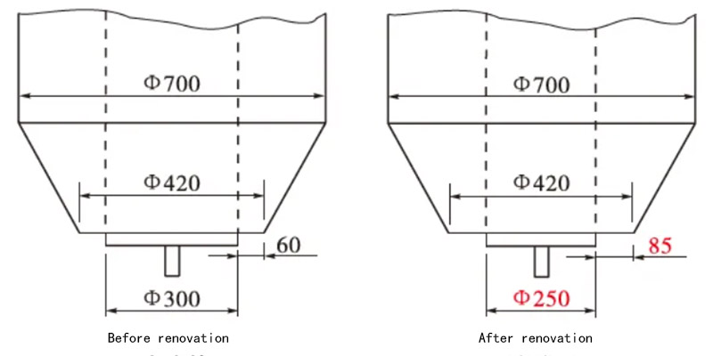
3.Ajuster le réservoir intérieur du système de chargement en vrac
Nous avons modifié le diamètre du réservoir intérieur de Φ300 mm à Φ250 mm. Cette modification augmente la surface de la section transversale du conduit de dépoussiérage dans le système de chargement en vrac. Il réduit également la résistance interne du tuyau de dépoussiérage. En outre, elle empêche l'apparition d'une pression positive dans le réservoir de stockage. L'expérience pratique a montré que la réduction du diamètre a peu d'impact sur le temps de chargement et de déchargement du ciment.
Résultats et évaluation
Après l'achèvement de la modification, il n'y a eu aucun cas de dégagement de poussière à l'entrée du camion de vrac pendant plus d'un an d'opérations de vrac. Nous n'avons pas non plus reçu de plaintes de clients concernant des amas de ciment dans le camion de transport en vrac. Cela a permis d'améliorer l'environnement de travail, de réduire les niveaux de particules dans la zone environnante et d'améliorer l'image de marque de l'entreprise. Le processus de modification technique a donné des résultats satisfaisants.
FAQ
1) Comment assurer la fiabilité à long terme du système de chargement en vrac après la mise à niveau technique ?
La stabilité à long terme est la clé du succès de la mise à niveau. Nos mesures comprennent :
Conception durable : Nous utilisons de l'acier à haute résistance et des composants de qualité, avec des pièces d'entraînement clés conçues pour s'adapter aux marges de travail, convenant aux opérations à haute intensité.
Surveillance intelligente : L'intégration d'un système d'alerte permet de surveiller en temps réel l'état de l'équipement, ce qui permet de détecter rapidement les problèmes potentiels et de réduire les temps d'arrêt imprévus.
Optimisation de la maintenance : La conception structurelle a été simplifiée pour permettre des réparations rapides ; nous proposons également des diagnostics à distance et des services d'inspection réguliers pour réduire les coûts de maintenance.
2. la mise à niveau technique du système de chargement en vrac affectera-t-elle la ligne de production existante ? Comment évaluer les risques et les coûts ?
Les mises à niveau techniques doivent concilier l'amélioration de l'efficacité et la continuité de la production. Notre processus d'évaluation comprend
Analyse de la demande : Menez une étude approfondie de votre processus de production pour identifier les goulets d'étranglement (tels que les équipements vieillissants ou les retards de contrôle) afin de vous assurer que la solution est adaptée avec précision.
Contrôle des risques : Utilisez une conception modulaire pour minimiser les temps d'arrêt ; fournissez un plan de mise en œuvre détaillé qui comprend un support d'équipement de secours pour éviter les interruptions de production.
Rapport coût-efficacité : La solution est rentable, les investissements initiaux étant rapidement amortis grâce à l'amélioration de l'efficacité et à la réduction de la consommation d'énergie.
3. notre système de chargement en vrac est lent, ce qui provoque des files d'attente. Comment pouvons-nous améliorer l'efficacité grâce à des améliorations technologiques ?
La faible efficacité du chargement est généralement due aux limites de la conception de l'équipement ou des systèmes de contrôle. Notre plan d'amélioration technique se concentre sur l'optimisation de la structure de la goulotte de déchargement et sur l'amélioration du système de contrôle automatique. Par exemple, nous avons adopté une tête de déchargement télescopique à plusieurs sections, qui peut s'ajuster automatiquement en fonction de la hauteur du véhicule, ce qui permet une connexion rapide et sûre et réduit le temps de préparation. Parallèlement, un système intelligent intégré de détection de niveau et de poids est intégré, ce qui permet d'ajuster automatiquement le débit du matériau, d'éviter la surcharge ou la sous-charge et de raccourcir considérablement le cycle de chargement individuel.