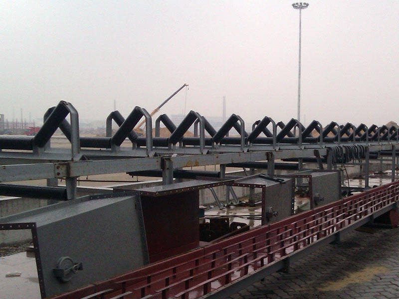
Rollers are a traditional transmission mechanism for ベルトコンベヤ. They have unique advantages and features. They also show good potential for technological development. However, factors like power parameters and technical limitations cause problems in the design process. Consequently, these problems restrict innovation. In future roller design, engineers must carefully analyze these issues. Then, they should take targeted measures to improve overall roller efficiency.

1. Overview of Belt Conveyor Rollers
The drive roller is a key component. It mainly transmits power and torque. Its stress situation is very complex. In the actual design process, engineers should not only use traditional methods to optimize the structure. They must also perform strength checks and stress analysis. Therefore, during optimization, they must fully consider many factors. These include the drive shaft structure, the support frame, and the load. Based on this, they can simplify the structure and establish a suitable stress model.
The bending roller has a different purpose. It mainly changes the direction of the conveyor belt. Additionally, it can tighten the conveyor belt. This action increases the wrap angle around the drive roller. Slippage often occurs between the belt and the drive roller. This slippage causes belt wear. In severe cases, it can burn the belt and even cause a fire. Therefore, adding a bending roller near the drive roller can effectively prevent slippage.
2. Existing Problems and Solutions
(1) Roller Wear Phenomenon
In conveyor systems, drive rollers usually have herringbone or diamond patterned rubber lagging. Conversely, bending rollers often have a flat rubber coating. For drive rollers, the rubber layer is typically vulcanized. Its thickness is usually over 15mm, and its hardness is not less than Shore 70°. For bending rollers, the rubber is also usually vulcanized. The thickness is over 10mm, and the hardness should not be less than Shore 60°. However, operational data shows that some bending rollers easily experience surface rubber detachment. This detachment changes the force on the belt during operation. As a result, the belt’s surface gets damaged, causing mistracking. This situation creates a safety hazard.
① Causes of Wear
Site inspections reveal that the design gap between the roller bracket and the roller is too small. Also, the longitudinal distance of the foundation anchor bolts is smaller than the bracket distance. During operation, accumulated material on the return belt is not cleaned. This buildup rubs against and abrades the rubber layer. The main cause of the wear is the design. The small spacing and short anchor bolt distance make it hard to clean material promptly. Onsite environmental factors are a secondary cause of damage.
② Corrective Measures
During design, engineers should lengthen the roller bracket longitudinally. Then, they should connect it to the conveyor frame to increase stability. Meanwhile, maintenance staff must promptly adjust the first and second rollers at the head section. This ensures optimal operation. After feeding ends, workers should clean the belt immediately. This ensures proper clearance around the rollers and foundation.
(2) Problem of Circular Weld Seam Fracture on Rollers
① Circular Weld Seam Fracture
When aligning the roller shell and the end plate, a recess is left. The weld is at the butt groove. During welding, the top interface can be easily welded. However, the lap joint is at the connected recess. Because the weld seam is too small, the welding wire cannot reach inside. This prevents root fusion, leading to lack of penetration. This is a serious welding defect. During operation, several locations on the roller bear high loads. During startup, the tension is also very high. Cracks from the lack of penetration will expand from the fusion area. Consequently, this causes the weld to crack.
② Solutions
To prevent cracking, place both the roller and end plate on a butt alignment fixture. Set a jack below to adjust the shell’s vertical position. Then, use a steel ruler on the outer surfaces to measure error at multiple points. Control the error within 1mm. Simultaneously, install screw rods on both fixture sides. Use these to adjust the gap between the end plate and the shell. Control it between 3mm and 4mm. This modification is simple. It ensures effective gap control. Thus, it guarantees better welding quality.

